Bluetooth Oscilloscope
Bluetooth oscilloscope
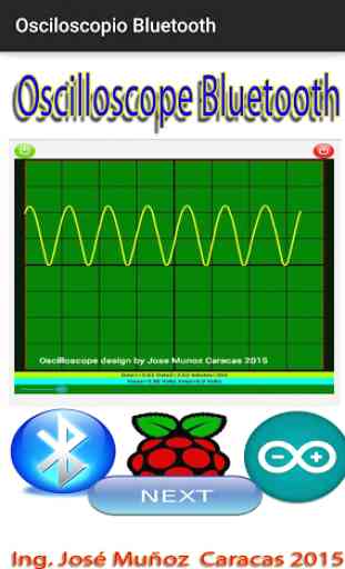
The oscilloscope Bluetooth application transforms your phone or tablet on an oscilloscope or voltmeter is connected via Bluetooth to a micro-controlled device such as a PIC, Arduino or Rasberry PI system. The Bluetooth Oscilloscope can display alternating signals (AC) and continuous signals (DC) on your mobile device securely as it connects wirelessly to your micro controller that captures the or DC signals AC and transmits it to your phone or tablet through Bluetooth.Visit the http://www.profjmunoz.blogspot.com/ page from within the application by pressing the "ONLINE TUTORIALS" icon where you can find tutorials on connecting ac signals and DC to a Arduino system and transmit it to your phone or tablet for view through Bluetooth Oscilloscope application.The oscilloscope Bluetooth application receives data from your micro system controlled in the following format:
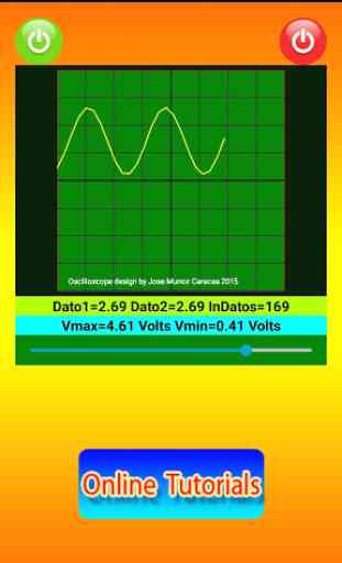
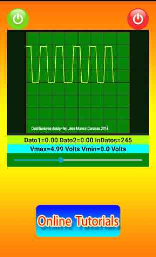
Received Signal = $ Dato1Dato2 #Example: Yes Data1 and Data2 = 4.25 = 60.5 receives $ 4.2560.5 #The value of data1 is plotted and the value of data2 is displayed.
When the oscilloscope turns on the green icon on the character "1" micro controlled system is shipped. When the red button is pressed off the character "0" is sent, these values can be used to control the processes that wish, such as a LED on or off, turn on or off sending data etc.Then the program is conducted in an Arduino system for sending data to your tablet or phone. 11 (RX) and 12 (TX): Arduino 1, a bluetooth module HC-06 was used in the pins. The DC or AC signal is introduced by the analog pin A0:
// include the library code:#include //String mensaje,mensaje3;#include SoftwareSerial mySerial(11, 12); // RX, TXchar inChar;// initialize the library with the numbers of the interface pinsLiquidCrystal lcd(8, 3, 4,6, 7,9);float dato1=1.25;float dato2=9.45;String tmp;unsigned long duracion1; unsigned long duracion2;
//clipping indicator variablesboolean clipping = 0;
//data storage variablesbyte newData = 0;byte prevData = 0;
//freq variablesunsigned int timer = 0;//counts period of waveunsigned int period;int frequency;
// Lee Los DATOS DE Voltaje Pin A0void readDatos();
void setup() { Serial.begin(9600); Serial.begin(9600); // set up the LCD's number of columns and rows: lcd.begin(20, 4); // Print a message to the LCD. lcd.setCursor(0,0); lcd.print("Osciloscopio Bth"); //pinMode(A1,INPUT); mySerial.begin(9600);}
void loop() { readDatos();// Calcula la Frecuencia de la Señal lcd.setCursor(0,2); lcd.print("Datos1="); lcd.print(dato1); lcd.print("Datos2="); lcd.print(dato2); enviarDatos(); while (mySerial.available() > 0) { inChar= (mySerial.read()); lcd.setCursor(0,1); lcd.print("Recibiendo="); lcd.setCursor(13,1); lcd.print(inChar); inChar=' '; } delay(100);}
// Lee los Datos e Voltajes Pueto Analogico A0 void readDatos(){ //dato1= analogRead (A0); dato1= (analogRead(A0)*0.00488); dato2=00.0;}// Enviar Datos al Dispositivo Androidvoid enviarDatos(){ mySerial.print('$'); readDatos(); mySerial.print(dato1); mySerial.print(dato1); // Aquí se púede enviar otro dato al Android mySerial.print ('#');}
The oscilloscope Bluetooth application transforms your phone or tablet on an oscilloscope or voltmeter is connected via Bluetooth to a micro-controlled device such as a PIC, Arduino or Rasberry PI system. The Bluetooth Oscilloscope can display alternating signals (AC) and continuous signals (DC) on your mobile device securely as it connects wirelessly to your micro controller that captures the or DC signals AC and transmits it to your phone or tablet through Bluetooth.Visit the http://www.profjmunoz.blogspot.com/ page from within the application by pressing the "ONLINE TUTORIALS" icon where you can find tutorials on connecting ac signals and DC to a Arduino system and transmit it to your phone or tablet for view through Bluetooth Oscilloscope application.The oscilloscope Bluetooth application receives data from your micro system controlled in the following format:
Received Signal = $ Dato1Dato2 #Example: Yes Data1 and Data2 = 4.25 = 60.5 receives $ 4.2560.5 #The value of data1 is plotted and the value of data2 is displayed.
When the oscilloscope turns on the green icon on the character "1" micro controlled system is shipped. When the red button is pressed off the character "0" is sent, these values can be used to control the processes that wish, such as a LED on or off, turn on or off sending data etc.Then the program is conducted in an Arduino system for sending data to your tablet or phone. 11 (RX) and 12 (TX): Arduino 1, a bluetooth module HC-06 was used in the pins. The DC or AC signal is introduced by the analog pin A0:
// include the library code:#include //String mensaje,mensaje3;#include SoftwareSerial mySerial(11, 12); // RX, TXchar inChar;// initialize the library with the numbers of the interface pinsLiquidCrystal lcd(8, 3, 4,6, 7,9);float dato1=1.25;float dato2=9.45;String tmp;unsigned long duracion1; unsigned long duracion2;
//clipping indicator variablesboolean clipping = 0;
//data storage variablesbyte newData = 0;byte prevData = 0;
//freq variablesunsigned int timer = 0;//counts period of waveunsigned int period;int frequency;
// Lee Los DATOS DE Voltaje Pin A0void readDatos();
void setup() { Serial.begin(9600); Serial.begin(9600); // set up the LCD's number of columns and rows: lcd.begin(20, 4); // Print a message to the LCD. lcd.setCursor(0,0); lcd.print("Osciloscopio Bth"); //pinMode(A1,INPUT); mySerial.begin(9600);}
void loop() { readDatos();// Calcula la Frecuencia de la Señal lcd.setCursor(0,2); lcd.print("Datos1="); lcd.print(dato1); lcd.print("Datos2="); lcd.print(dato2); enviarDatos(); while (mySerial.available() > 0) { inChar= (mySerial.read()); lcd.setCursor(0,1); lcd.print("Recibiendo="); lcd.setCursor(13,1); lcd.print(inChar); inChar=' '; } delay(100);}
// Lee los Datos e Voltajes Pueto Analogico A0 void readDatos(){ //dato1= analogRead (A0); dato1= (analogRead(A0)*0.00488); dato2=00.0;}// Enviar Datos al Dispositivo Androidvoid enviarDatos(){ mySerial.print('$'); readDatos(); mySerial.print(dato1); mySerial.print(dato1); // Aquí se púede enviar otro dato al Android mySerial.print ('#');}
Category : Education
Related searches
Working fine but an English tutorial is needed in supporting website. Nice job.