& logics
New beta release with 7 segment display is available:https://play.google.com/apps/testing/com.hexastyle.andlogics
& logics is a logic circuit simulator with an integrated scheme editor and a waveform browser.Currently available schematic components: Transistors: NMOS, PMOSLogic gates: buffer, inverter, and, nand, or, nor, exor, exnor, tri-state buffer and inverterFlip flops: D latch, edge triggered D, JK flip flops, monostableMultiplexers: 2 to 1, 4 to 1, 8 to 1.Demultiplexers: 1 to 2, 1 to 4, 1 to 8Indicators: LED, oscilloscope probeDisplays: decimal, hexadecimalSwitches: toggle button, push buttonConstants: high and low.
Scheme editor features: custom subcircuit (black box), context sensitive menu, autorouter, 7 steps undo/redo, labels for far connections, automatic enlarge on selection, cloning, rotating, locked and unlocked move, vertical and horizontal alignment, move to center.
The digital circuit simulator works with three logic levels and three impedance values. They are low, undefined and high.Wires optionally can display logic levels.Switch level modelling, gate level modelling and complex device level modelling can be mixed in a circuit.The simulator detects run time errors and puts error messages on the schematic.Detected errors are:Temporary short circuit conditions. When connected outputs have different or undefined levels and have low or undefined impedance.Spike detection. When an input receives an impulse shorter than the configured value.Flip flop setup, hold, recovery, resume time violations. Flip flops may enter a metastable state in these cases.
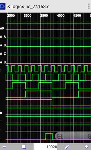
The waveform browser is a virtual digital oscilloscope. The current features are: start, stop time, buffer length setting, time shift and zoom, display of logical low, high, and undefined states.
The 3.x releases contain HDL extension. It is possible to describe a circuit in a box using a very small subset of Verilog. The gates.s demo loads the following module from simple.v file:
module smpl_circuit (A,B,AND,NAND,OR,NOR,XOR,XNOR,BUF,NOT);input A,B;output AND,NAND,OR,NOR,XOR,XNOR,BUF,NOT;and #10 g0(AND,A,B);nand #10 g1(NAND,A,B);or #10 g2(OR,A,B);nor #10 g3(NOR,A,B);xor #10 g4(XOR,A,B);xnor #10 g5(XNOR,A,B);buf #10 g6(BUF,A);not #10 (NOT,A);endmodule
and the test1.v file:
module circuit(A,B,C,y);input A,B;output y;wire e;and #30 g1(e,A,B); or #30 g2(y,e,C);endmodule
There is no runtime error detection inside the boxes.Only the first compile time error is displayed.
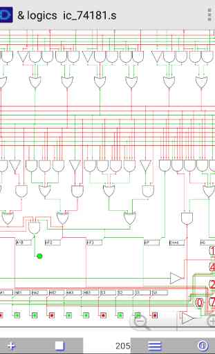
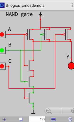
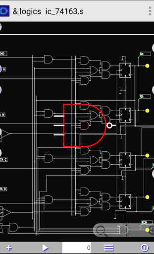
The program comes with built in demo circuits. They help you to get started quickly. See http://www.hexastyle.com/home/andlogics/first-3-steps for details.You can easily simulate, analyse and modify operation and timing of the examples.Built in examples: 74160, 74163 synchronous counter74180 parity generator checker74181 4 bit ALU74147, 74148 priority encodertransistor level modelling of CMOS gatesMore examples e.g. binary adder, Johnson counter can be downloaded from here:http://www.hexastyle.com/home/andlogics/download-examples
& logics is a logic circuit simulator with an integrated scheme editor and a waveform browser.Currently available schematic components: Transistors: NMOS, PMOSLogic gates: buffer, inverter, and, nand, or, nor, exor, exnor, tri-state buffer and inverterFlip flops: D latch, edge triggered D, JK flip flops, monostableMultiplexers: 2 to 1, 4 to 1, 8 to 1.Demultiplexers: 1 to 2, 1 to 4, 1 to 8Indicators: LED, oscilloscope probeDisplays: decimal, hexadecimalSwitches: toggle button, push buttonConstants: high and low.
Scheme editor features: custom subcircuit (black box), context sensitive menu, autorouter, 7 steps undo/redo, labels for far connections, automatic enlarge on selection, cloning, rotating, locked and unlocked move, vertical and horizontal alignment, move to center.
The digital circuit simulator works with three logic levels and three impedance values. They are low, undefined and high.Wires optionally can display logic levels.Switch level modelling, gate level modelling and complex device level modelling can be mixed in a circuit.The simulator detects run time errors and puts error messages on the schematic.Detected errors are:Temporary short circuit conditions. When connected outputs have different or undefined levels and have low or undefined impedance.Spike detection. When an input receives an impulse shorter than the configured value.Flip flop setup, hold, recovery, resume time violations. Flip flops may enter a metastable state in these cases.
The waveform browser is a virtual digital oscilloscope. The current features are: start, stop time, buffer length setting, time shift and zoom, display of logical low, high, and undefined states.
The 3.x releases contain HDL extension. It is possible to describe a circuit in a box using a very small subset of Verilog. The gates.s demo loads the following module from simple.v file:
module smpl_circuit (A,B,AND,NAND,OR,NOR,XOR,XNOR,BUF,NOT);input A,B;output AND,NAND,OR,NOR,XOR,XNOR,BUF,NOT;and #10 g0(AND,A,B);nand #10 g1(NAND,A,B);or #10 g2(OR,A,B);nor #10 g3(NOR,A,B);xor #10 g4(XOR,A,B);xnor #10 g5(XNOR,A,B);buf #10 g6(BUF,A);not #10 (NOT,A);endmodule
and the test1.v file:
module circuit(A,B,C,y);input A,B;output y;wire e;and #30 g1(e,A,B); or #30 g2(y,e,C);endmodule
There is no runtime error detection inside the boxes.Only the first compile time error is displayed.
The program comes with built in demo circuits. They help you to get started quickly. See http://www.hexastyle.com/home/andlogics/first-3-steps for details.You can easily simulate, analyse and modify operation and timing of the examples.Built in examples: 74160, 74163 synchronous counter74180 parity generator checker74181 4 bit ALU74147, 74148 priority encodertransistor level modelling of CMOS gatesMore examples e.g. binary adder, Johnson counter can be downloaded from here:http://www.hexastyle.com/home/andlogics/download-examples
Category : Education
Related searches
Reviews (11)
ab. k.
Aug 28, 2017
It's nice.
Eri. P.
Apr 30, 2017
Very nice job on this dev. Including the karnaugh equations with the logic inputs/outputs makes it an excellent logic learning tool and the scope tool is brilliant. Thanks n God bless Dev!
Rah. c.
Apr 3, 2017
it's vary nice
Ahm. B. Y.
Nov 21, 2016
I need 7 segment display half adder and full adder other logic apps doesnt have copy function this is good
Wag. L.
Sep 22, 2016
Need display 7 segments.
Ste. F.
May 27, 2016
Still evaluating ...Samsung Note 4
Shr. S.
Nov 5, 2015
Very bad app
A. G. u.
Aug 20, 2017
but can u add decoders & encoders.
Far. A.
Dec 20, 2016
But how do u link the cables ? Ive bein strugglin for so long to do that please :P
van. a.
Sep 29, 2017
No question info? Good chances notoriety look over for only a good way
No longer supported. HELP no longer works. Cant use without HELP