SCADAfeathery for Modbus
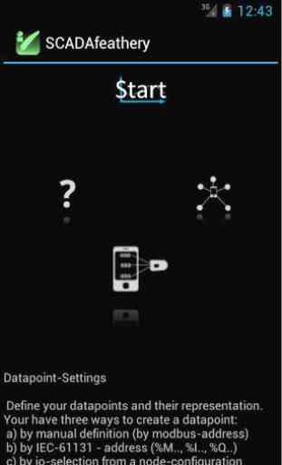
You have a Modbus device and want to visualize it by a few easy steps?Are you an owner of WAGO (P-)FC series 750/758?Are your writing CoDeSys 2.3 programms on WAGO-devices and want to see the calculation results on your android device?Then this application is that what you are looking for.After only 3 steps the definition of the visualization is complete: 1) Define your Modbus network. 2) Create data points. 3) Define the representation of the data points
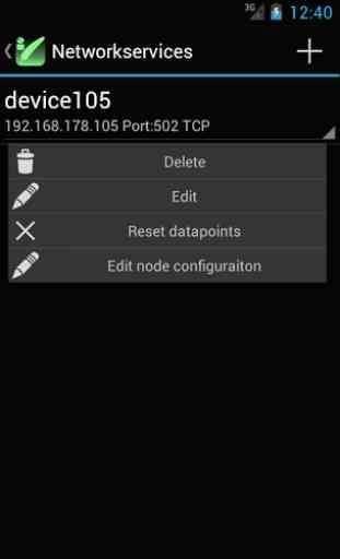
You can define any number of devices on the network.The devices (called network services) are stored in the application,and can be used later. For each device (network service), you can assign its data points.The definition of a datapoint consists of the following parameters:
- Designation of the datapoint
- Datatype of the datapoint (based on IEC61131-Datatypes)
- Datatype STRING requiers the length in bytes additionaly
- Read-Defintion: FC-Code (FC1, FC2, FC3, FC4)
- Read-Definition: modbus address (register or coil, depends on FC-Code)
- Read-Definition: bit offset, within the addressed modbus register or coil
- Write-Defintion: FC-Code (FC5, FC6, FC15, FC16)
- Write-Definition: modbus address (register or coil, depends on FC-Code)
- Write-Definition: bit offset, within the addressed modbus register or coilFor WAGO-Devices this parameters are filled out automaticaly.
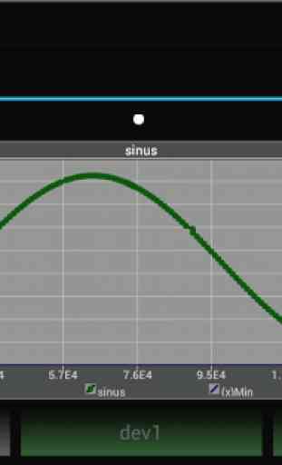
Each data point can be visualized by (at the moment) 4 presentation items: + Textbox + Slider (0..100) + Switch + XY-PlotYour are able to scale the values by the linear polynom (f(x)=m*x+b).You can define min/max-ranges, that are monitored at the runtime.There is a constant monitoring of the data point availability , you will be notifiedif the datapoint is not accessable anymore.
Modbus-communication
The communication is possible through Wifi and 3G/4G
- Networks.Following modbus function codes are supported:FC1, FC2, FC3, FC4,FC5,FC6,FC15,FC16.An real-time algorithm used for communication task guarantees that the calculated cycle-time for each communication-job will be kept.The cycle-time is linearly proportional to the number of datapoints within the perspective.
Special features for WAGO-Devices
This appliation contains a database with all at the moment existing WAGO-Controllers and Couplersof the series 750/758. There is also modbus process image data about all terminals of the series 750/753.
You have defined your WAGO node already as network service?Then mark the discovered devices as WAGO device and scan the node.The connected terminals will be recognized and the full process image for modbus will be stored.Now you no longer have to calculate the address of the terminal in the process image.Just select the terminal and the channel of the terminal from the node description and make it to a data point.Do you have a PFC (programmable WAGO coupler)? Then it is possible to you to define a datapoint just byentereing of the IEC61131-address. Just enter the %I, %Q, %M address of your programm variable and the application converts this information into accoridn modbus-address on the network.Hint: Consider the PI-Assignment-Setting from CoDeSys if you want the write-access to kbus-terminals.
You can define any number of devices on the network.The devices (called network services) are stored in the application,and can be used later. For each device (network service), you can assign its data points.The definition of a datapoint consists of the following parameters:
- Designation of the datapoint
- Datatype of the datapoint (based on IEC61131-Datatypes)
- Datatype STRING requiers the length in bytes additionaly
- Read-Defintion: FC-Code (FC1, FC2, FC3, FC4)
- Read-Definition: modbus address (register or coil, depends on FC-Code)
- Read-Definition: bit offset, within the addressed modbus register or coil
- Write-Defintion: FC-Code (FC5, FC6, FC15, FC16)
- Write-Definition: modbus address (register or coil, depends on FC-Code)
- Write-Definition: bit offset, within the addressed modbus register or coilFor WAGO-Devices this parameters are filled out automaticaly.
Each data point can be visualized by (at the moment) 4 presentation items: + Textbox + Slider (0..100) + Switch + XY-PlotYour are able to scale the values by the linear polynom (f(x)=m*x+b).You can define min/max-ranges, that are monitored at the runtime.There is a constant monitoring of the data point availability , you will be notifiedif the datapoint is not accessable anymore.
Modbus-communication
The communication is possible through Wifi and 3G/4G
- Networks.Following modbus function codes are supported:FC1, FC2, FC3, FC4,FC5,FC6,FC15,FC16.An real-time algorithm used for communication task guarantees that the calculated cycle-time for each communication-job will be kept.The cycle-time is linearly proportional to the number of datapoints within the perspective.
Special features for WAGO-Devices
This appliation contains a database with all at the moment existing WAGO-Controllers and Couplersof the series 750/758. There is also modbus process image data about all terminals of the series 750/753.
You have defined your WAGO node already as network service?Then mark the discovered devices as WAGO device and scan the node.The connected terminals will be recognized and the full process image for modbus will be stored.Now you no longer have to calculate the address of the terminal in the process image.Just select the terminal and the channel of the terminal from the node description and make it to a data point.Do you have a PFC (programmable WAGO coupler)? Then it is possible to you to define a datapoint just byentereing of the IEC61131-address. Just enter the %I, %Q, %M address of your programm variable and the application converts this information into accoridn modbus-address on the network.Hint: Consider the PI-Assignment-Setting from CoDeSys if you want the write-access to kbus-terminals.
Category : Productivity
Related searches