

Shaft Alignment (test version)
Axis will calculate the value necessary to move the motor in the three-dimensional calculation to the alignment.
Minimum scale of the calculation of this trial is 0.1mm. By purchasing the final version makes calculations to 0.001mm.
Caustic ratio as other equipment should not be compared. The reliability of this product is not inferior to other expensive equipment.
Terms of Use (Important)
1 (such as a magnet or a vise chain), a dial gauge with a device that can fixed to the motor shaft
Each must be one by one.
If the above devices can not use the app.
2. The motor is fixed to the compact device or followed up
If there is not enough space to mount the gauge can not be used.
Yireolttae should you buy an app.
How to use
1. Measure the dimensions of the frame.
Reducer shaft end of the motor shaft end (a position not exactly gauge needle touches)
The front end of the motor shaft and the stationary part of the motor Central
The center of the central portion of the front and rear fixed portions fixed
2 and secure the gauge to the motor shaft placing a dial gage on the reduction gear shaft end.
Turn 90 degrees to the axis of the motor every measure to gauge the value of your place.
3 and securing the gauge to the reduction gear shaft placing a dial gauge to the motor shaft end portion.
Reducer shaft clockwise by 90 degrees every measure to gauge the value of your place.
The length of the unit used here is the dimension of the framework, all calculation results in mm.
The primary measure ready
Sikkim fixing the gauge body to the right of the motor shaft
The dial gauge needle must be placed in the reducer shaft end
Primary measurement
1. Create a gauge of position of the gauge is 360 degrees when the first square "OK" button.
If the check does not put a value to recognize the value of "0"
2. "OK" button after filling the motor shaft to the second square and then rotated 90 degrees right.
3.180 even after rotating in the direction "OK" button to create a third square.
Figure 4.270 "OK" button, then right and then rotate in the direction of the fourth square. Then move on to the next measurement screen.
Secondary measures prepared
Sikkim fixing the gauge body to the left speed reducer shaft
The dial gauge needle must be placed on the motor shaft end
Secondary measurement
1. "OK" button to create a gauge value in the first square. If the check does not put a value to recognize the value of "0"
2. "OK" button after filling the motor shaft to the second square and then rotated 90 degrees right.
3.180 even after rotating in the direction "OK" button to create a third square.
Figure 4.270 "OK" button, then right and then rotate in the direction of the fourth square. This results to the screen.
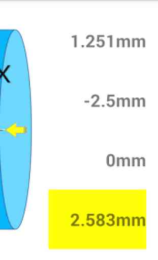
Purpose: The alignment value calculator when connecting a large-sized motors and machinery.
This allows calculation of the motor shaft axes and the machine to be a straight line.
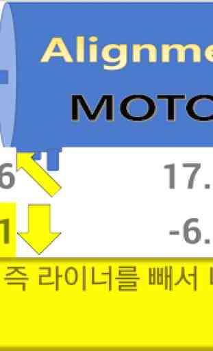
If adjustment is replaced by a liner of a thickness calculated under the motor.
Minimum scale of the calculation of this trial is 0.1mm. By purchasing the final version makes calculations to 0.001mm.
Caustic ratio as other equipment should not be compared. The reliability of this product is not inferior to other expensive equipment.
Terms of Use (Important)
1 (such as a magnet or a vise chain), a dial gauge with a device that can fixed to the motor shaft
Each must be one by one.
If the above devices can not use the app.
2. The motor is fixed to the compact device or followed up
If there is not enough space to mount the gauge can not be used.
Yireolttae should you buy an app.
How to use
1. Measure the dimensions of the frame.
Reducer shaft end of the motor shaft end (a position not exactly gauge needle touches)
The front end of the motor shaft and the stationary part of the motor Central
The center of the central portion of the front and rear fixed portions fixed
2 and secure the gauge to the motor shaft placing a dial gage on the reduction gear shaft end.
Turn 90 degrees to the axis of the motor every measure to gauge the value of your place.
3 and securing the gauge to the reduction gear shaft placing a dial gauge to the motor shaft end portion.
Reducer shaft clockwise by 90 degrees every measure to gauge the value of your place.
The length of the unit used here is the dimension of the framework, all calculation results in mm.
The primary measure ready
Sikkim fixing the gauge body to the right of the motor shaft
The dial gauge needle must be placed in the reducer shaft end
Primary measurement
1. Create a gauge of position of the gauge is 360 degrees when the first square "OK" button.
If the check does not put a value to recognize the value of "0"
2. "OK" button after filling the motor shaft to the second square and then rotated 90 degrees right.
3.180 even after rotating in the direction "OK" button to create a third square.
Figure 4.270 "OK" button, then right and then rotate in the direction of the fourth square. Then move on to the next measurement screen.
Secondary measures prepared
Sikkim fixing the gauge body to the left speed reducer shaft
The dial gauge needle must be placed on the motor shaft end
Secondary measurement
1. "OK" button to create a gauge value in the first square. If the check does not put a value to recognize the value of "0"
2. "OK" button after filling the motor shaft to the second square and then rotated 90 degrees right.
3.180 even after rotating in the direction "OK" button to create a third square.
Figure 4.270 "OK" button, then right and then rotate in the direction of the fourth square. This results to the screen.
Purpose: The alignment value calculator when connecting a large-sized motors and machinery.
This allows calculation of the motor shaft axes and the machine to be a straight line.
If adjustment is replaced by a liner of a thickness calculated under the motor.
Category : Productivity
Related searches